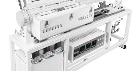
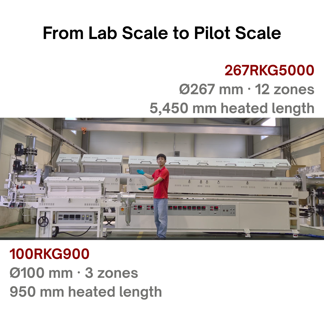
Developing Continuous Processes with Four Separate Furnace Sections and 12 Independently Controlled Heating Zones
From Laboratory Heating Programs to Continuous Processing
Most lab heat treatments aren’t a single step. A powder might need to dry at a lower temperature first, then release volatile compounds in an intermediate stage, and only after that go through its main treatment at a higher temperature.
In a batch furnace, that’s easy to manage. You program a temperature schedule, the material stays put, and the furnace temperature changes around it.
Continuous processing turns this around. Now the material is what moves, and every part of its path through the equipment adds to its thermal history. The temperature of each section, the transition from one section to the next, and the time the material spends in the tube all have to work together.
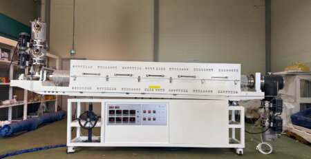
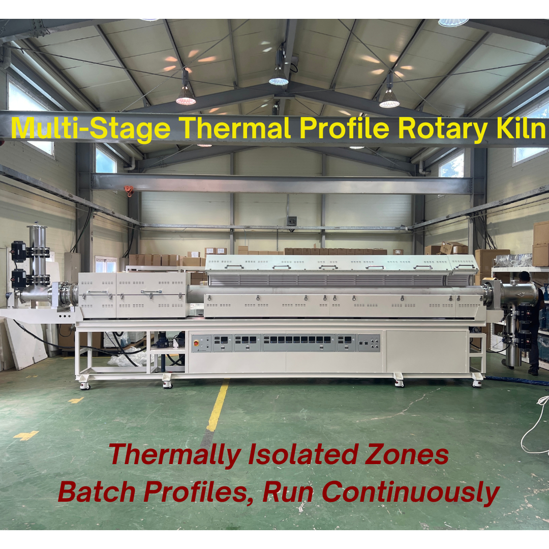
That’s the problem SH Scientific’s multi-stage thermal profile rotary kiln is designed to help researchers work through. This pilot-scale rotary kiln combines four physically separate furnace sections, adjustable spacing between them, and 12 independently controlled heating zones, each able to reach 800°C.
Why Separate Furnace Sections Matter
Multiple heating zones let you run different temperatures along a rotary kiln. The catch is that neighboring zones still share heat. A hotter zone can bleed heat into the cooler one next to it, which blurs the boundary between process stages and makes transitions harder to control.
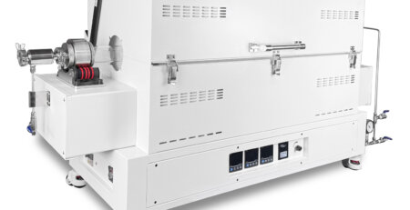
The SH-FU-267RKG5000 multi-stage thermal profile rotary kiln deals with this by splitting the heated length into four separate furnace sections along one continuous rotating tube. Each section sits on linear rails, so you can move it and change the spacing between sections, within the equipment’s mechanical limits.
The gaps between sections are unheated. Cooling fans at those gaps are designed to help cut down heat transfer from one stage to the next.
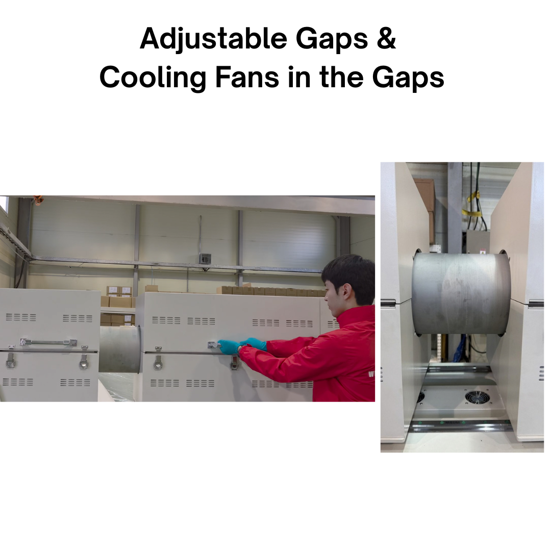
In practice, this gives you one more variable to work with besides zone setpoints: the physical distance between heating sections.
Keep in mind that the temperature profile the material actually sees still depends on how you run the system. Conduction along the tube, how much material is loaded, gas flow, and the way the material moves all affect how a sample heats up and cools down on its way through the kiln.
Four Furnace Sections and 12 Heating Zones
Here’s how the 12 heating zones are split across the four sections:
| Furnace section | Heating zones | Maximum temperature per zone |
|---|---|---|
| Section 1 | 1 | 800°C |
| Section 2 | 2 | 800°C |
| Section 3 | 8 | 800°C |
| Section 4 | 1 | 800°C |
Every zone has its own program controller and K-type temperature sensor, and every zone can reach 800°C.
Each section can take on a different job in the process. For example, the first section might handle preheating or drying, the second an intermediate treatment, and the longer third section the main thermal treatment. The fourth, near the discharge end, can provide post-heating.
Those roles are only examples. They don’t mean the first, second, or fourth section is limited to a lower maximum temperature. You can build the temperature settings your process needs within the available configuration, instead of treating the whole heated length as one uniform-temperature region.
Developing the Temperature Profile
This is where a staged temperature profile becomes useful: when a material needs different conditions as the treatment goes on.
The first section might drive off moisture before the material reaches its decomposition stage. A later section can then supply the temperature needed for the reaction or phase transformation you’re after. And if the process gives off condensable vapors, post-heating near the outlet can help limit condensation in that area.
The right sequence depends on your material and the result you want. A few questions make a good starting point:
- Does the material need a separate drying stage?
- At what temperature does significant gas or vapor release begin?
- How much time does the main treatment need?
- Does a gradual transition between stages work better than a sharper one?
- What conditions does the material need before it enters the receiving system?
Zone setpoints give you a starting point for these studies. From there, check them against how the material actually responds, including its temperature history and the properties of the product you recover.
Residence Time and Material Movement
Temperature is only half the story in a continuous process. The material also has to spend enough time under the right conditions.
On the SH-FU-267RKG5000, tube rotation is adjustable from 0 to 5 rpm and tilt from 0 to 3°. A screw feeder delivers material into the rotating tube.
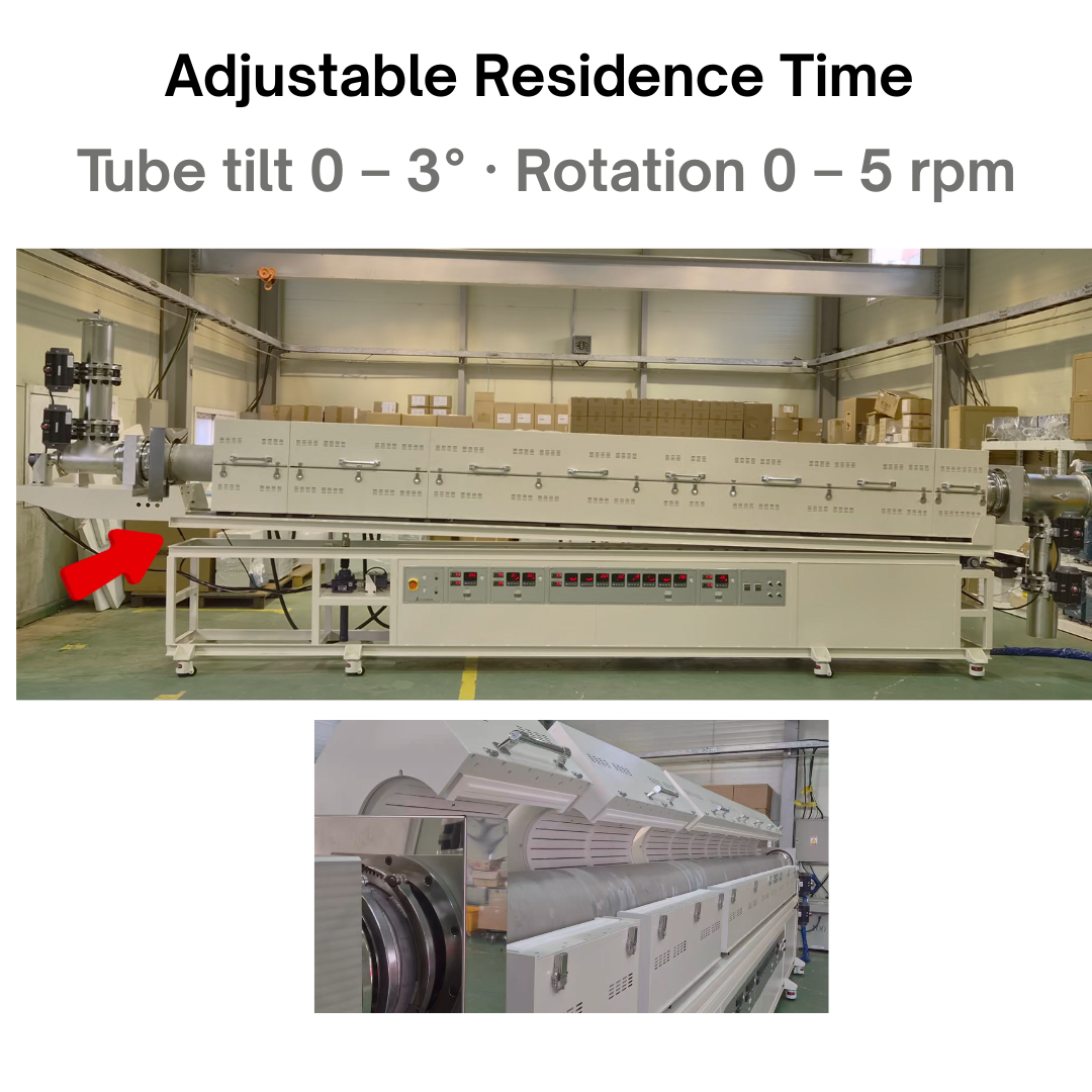
When you’re developing a process, look at rotation, inclination, and feed rate together with:
- Particle size and bulk density
- Flowability and tendency to stick or agglomerate
- Material loading inside the tube
- Changes in material properties during heating
- Required time at the treatment temperature
One point that’s easy to miss: changing the spacing between furnace sections changes the length of the unheated gaps, but it doesn’t set the residence time in each stage on its own.
Residence time should be confirmed with your actual material under real operating conditions. A longer tube gives you more room to lay out treatment stages, but tube length by itself doesn’t tell you the processing time or throughput.
Continuous Feeding and Material Recovery
A pilot-scale system is only useful if it handles material as well as it handles heat.
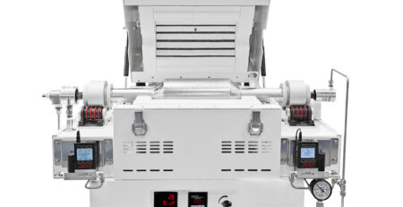
On the feed side, two 10-liter vessels and pneumatic butterfly valves form an airlock, and a screw feeder meters material into the process tube. The airlock is designed to let you replenish the feed while limiting direct exchange with the surrounding atmosphere.
At the discharge end, two 10-liter receiving vessels with pneumatic valves let you collect processed material during operation.
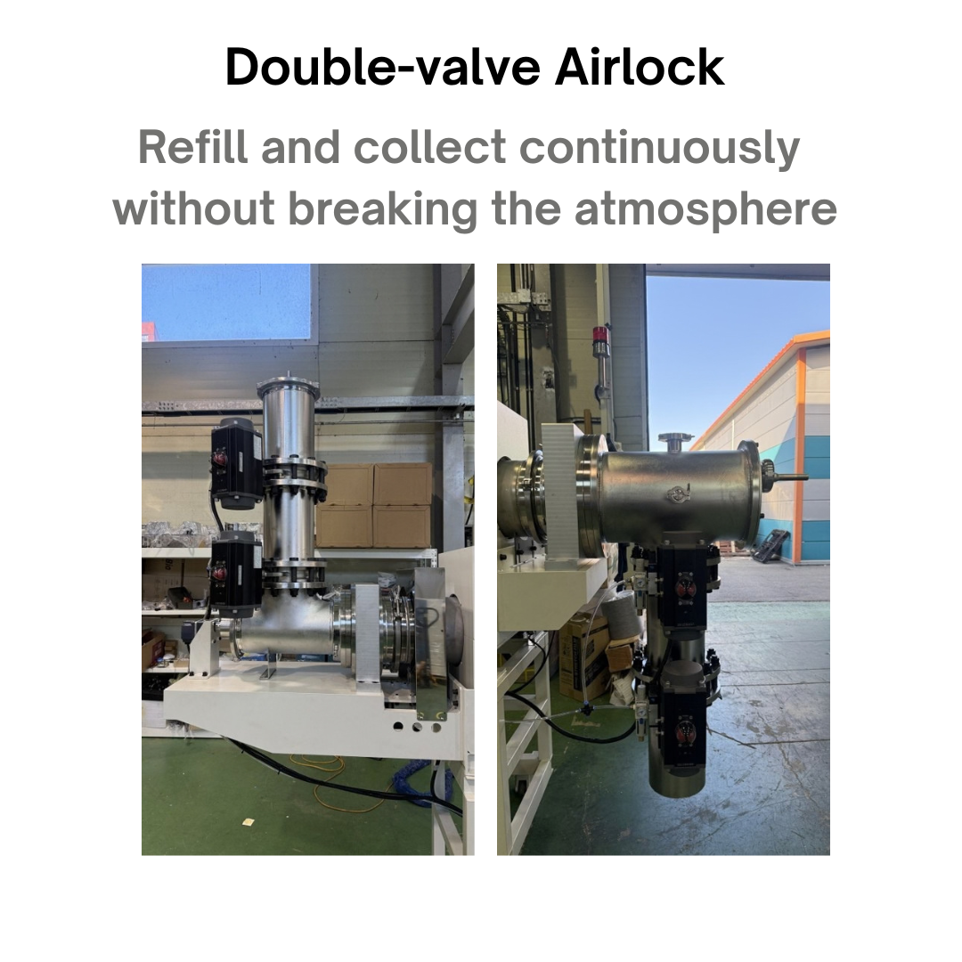
The discharge assembly also has an exhaust connection and a view port. Heating near the outlet addresses condensation, while a cooling coil connected to a chiller cools the material in the secondary receiving vessel.
These two features do different jobs. Post-heating controls conditions along the discharge path, and the cooling system brings down the temperature of the material you’ve collected.
Atmosphere requirements, valve operation, and exhaust handling should still be reviewed for each specific process.
Key Configuration Details
Here’s the reference configuration for the SH-FU-267RKG5000:
| Parameter | Reference configuration |
|---|---|
| Maximum zone temperature | 800°C in each of 12 independently controlled zones |
| Furnace arrangement | Four separate sections with adjustable spacing |
| Process tube | Seamless Alloy 601 |
| Nominal tube dimensions | 267 mm outside diameter / 258 mm inside diameter Approximately 10.5 in / 10.2 in |
| Total tube length | 6,180 mm (approximately 20.3 ft) |
| Tube rotation | 0–5 rpm |
| Tube inclination | 0–3° |
| Feeding vessels | Two 10-liter vessels |
| Receiving vessels | Two 10-liter vessels |
Note that the total tube length includes the portions outside the furnace sections, so it isn’t the same as the heated length.
Every system is built to order. Furnace count, zone layout, tube material, and tube length can all be reviewed against your intended process, and electrical supply and site utilities should be confirmed during configuration as well.
Applications for Staged Thermal Processing
This configuration is meant for powder and granular material studies that need several thermal stages, all within an 800°C maximum zone temperature. Areas worth evaluating include:
- Drying and thermal decomposition of material precursors
- Selected battery-material precursor treatments and recycling pretreatment
- Catalyst precursor decomposition and thermal treatment
- Biomass pyrolysis and carbonization studies
- Ceramic precursor calcination within the available temperature range
That said, the process name alone doesn’t tell you whether it’s a good fit. The material has to be compatible with the tube, the required temperature has to fall within what the equipment can do, and the atmosphere and exhaust system have to suit the reaction.
Pilot trials help answer the real question: does your proposed sequence produce the material you want, and does it do so consistently under continuous feeding?
Questions Researchers and Process Engineers Ask
Developing the Next Stage of Your Process
Moving from batch research to continuous processing starts with a clear picture of how your material behaves through the whole heating and handling sequence.
SH Scientific’s multi-stage pilot-scale rotary kiln brings adjustable furnace spacing, independent zone control, and continuous material handling together in one system. That lets you investigate process conditions and gather the data you need for the next stage of equipment development.
Contact SH Scientific to talk through your material, target throughput, temperature profile, and atmosphere requirements. Those details are the starting point for evaluating a rotary kiln configuration for your process.